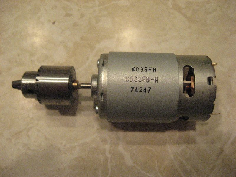
 12V DC 550 motor, 22,000RPM
 Complete Z axis assembly
 Anti-backlash nut design
 Nearly-complete XY plane
 Measured, marked, cut by hand...
Accuracy is one of my strengths
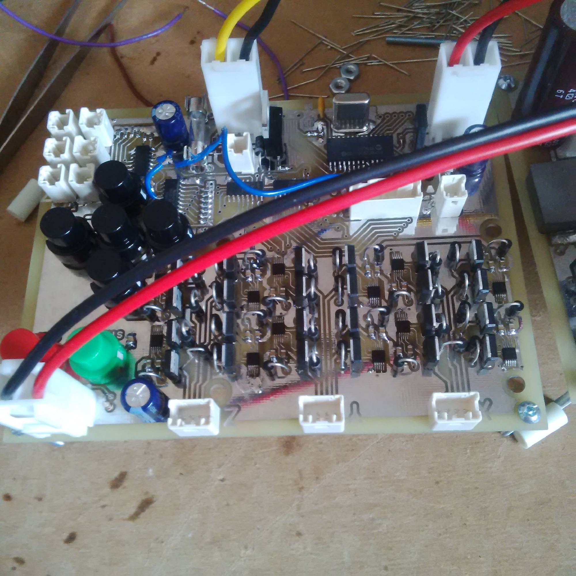
 Controls for motors & LCD
 Switched mode power supply
 Soft start power-up circuit